Friday, 16 November 2018

COOLING AND SOLIDIFICATION

Definition :- 

                           Understanding the rates of cooling and solidification in laminar flows down sloping channels is central to predicting the advance of lava flows.
Image result for COOLING AND SOLIDIFICATIONThe mechanisms involved include thermal convection and a competition between shear strain rate and the rate of formation of solid at the chilled surface of the flow. We report experiments in which polyethylene glycol wax flows in a laminar fashion down an inclined, open channel of rectangular cross-section under cold water. 
Image result for COOLING AND SOLIDIFICATION
Two distinctly different flow regimes are recognized: ‘tube’ flow in which solidification of the flow surface creates a stationary roof while melt continues to flow through a relatively well-insulated ‘tube’ beneath, and a ‘mobile crust’ regime in which a solid surface crust develops only in the centre of the channel. 


Image result for COOLING AND SOLIDIFICATION In the latter regime the crust is carried down the channel, separated from the walls by crust-free shear regions in which cooling produces only dispersed fragments of solid owing to the effects of shearing. This flow structure is quasi-invariant over a large distance downstream. 
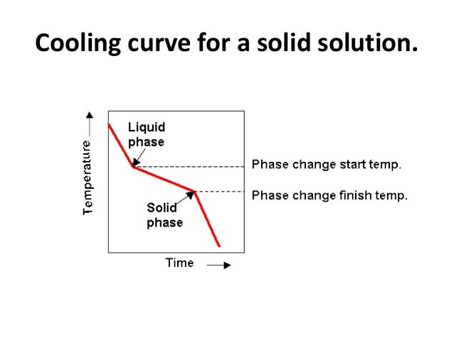
                  Image result for COOLING AND SOLIDIFICATIONWe show that thermal convection takes place in organized rolls that have axes aligned with the shear flow, and conclude that transition between the two flow regimes occurs at a critical value of the combined parameter
     Ï‘=ψ(\it Ra/R0)1/3, where Ïˆ=U0ts/H0 is the ratio of a surface solidification timescale ts to a shearing timescale H0/U0, H0 and U0 are the flow depth and centreline surface velocity in the absence of solidification, {\it Ra} is a Rayleigh number and R0 is a constant.

Image result for COOLING AND SOLIDIFICATION

Cooling Curves
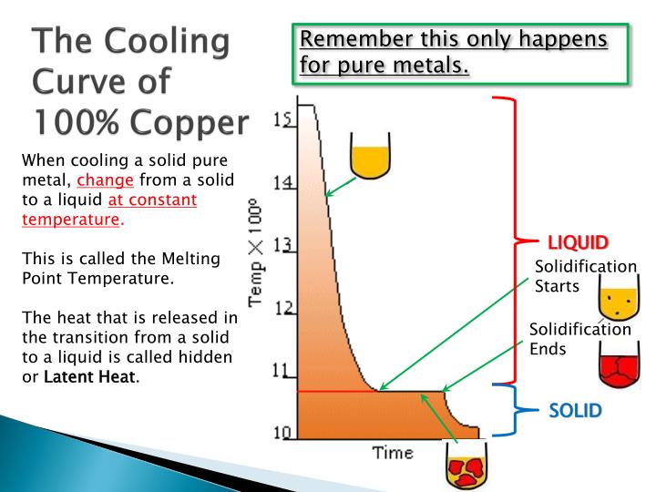
Plotting a graph of Temperature and Time as liquid metal cools will produce a. Such graphs serve to illustrate the behaviour of metal as it cools and what changes occur at different temperatures

File:LeadandTinCoolingCurves.png
Typical COOLING CURVE for pure metals will be a stepped graph as shown. Heat is being lost throughout the process but at the point of freezing the temperature doesn't fall because the freezing process will liberate heat at exactly the same rate that it is being lost to the surroundings.
                 This is the result of energy being released when new atomic bonds are formed formed (e.g changing states from Liquid to Solid Lead or Tin).

Phase Change: Cooling and Solidification of Metal :- 

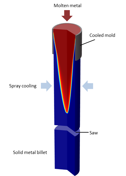
         Modeling phase change is important for many thermal processes, ranging from the food industry to the metal processing industry. The Heat Transfer Module offers a dedicated interface for modeling the characteristics of phase change. It uses the apparent heat capacity method, which we introduce here.


Model depicting the continuous casting process.


Example: Continuous Casting
Phase change is a transformation of material from one state of matter to another due to a change in temperature. Phase change leads to a sudden variation in the material properties and involves the release or absorption of latent heat. We can use the Heat Transfer Module to model this type of phase change. Let’s start with an example.






Tuesday, 13 November 2018

LASER BEAR MACHINING ( LSM )

laser beam machining 
A laser beam machining device having aspherical lenses for uniformity of the cross section intensity of a laser beam emitted from a laser oscillator
, Image result for LASER BEAM MACHINING DEFINITION
and converging optical unit composed of a plurality of converging lenses disposed to be aligned in single or plural rows on a plane in the optical path of the uniform laser beam, whereby uniform machining can be performed in the middle and at the edges of the machining area and the allowable machining area can be made wider.
Image result for LASER BEAM MACHINING DEFINITION

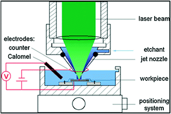
Laser Beam Machining (LBM) is a form of machining process in which laser beam is used for the machining of metallic and non-metallic materials. In this process, a laser beam of high energy is made to strike on the workpiece, the thermal energy of the laser gets transferred to the surface of the w/p (workpiece). The heat so produced at the surface heats, melts and vaporizes the materials from the w/p.Light amplification by stimulated emission of radiation is called LASER.Image result for LASER BEAM MACHINING DEFINITION
                                            It works on the principle that when a high energy laser beam strikes the surface of the workpiece. The heat energy contained by the laser beam gets transferred to the surface of the w/p. This heat energy absorbed by the surface heat melts and vaporizes the material from the w/p. In this way the machining of material takes place by the use of laser beam.              
Image result for LASER BEAM MACHINING DEFINITION


A high-quality, high-speed micromachining process is important for implementing a cost effective solution on a manufacturing machine. Use of lasers for micromachining has grown steadily over the years, and by 2015 laser micromachining is expected to be a $752M market.1 In recent years there also has been rapid advancement in laser technology. The energy available per pulse and the pulse repetition frequency (PRF) of diode-pumped solid-state (DPSS) nanosecond ultraviolet (UV) lasers have increased dramatically. Efficient use of the available energy from a laser source is important to achieve maximum material removal and minimal thermal damage for any laser micromachining application.              Image result for LASER BEAM MACHINING DEFINITION                                                                                      The use of the optimal energy density, or fluence (J/cm2), for material removal is especially important for short pulse-width lasers. Compared to longer pulse widths, a shorter pulse results in shallower thermal penetration depth, which means smaller heated volume and hence less residual heat-affected zone (HAZ) in the material.Image result for LASER BEAM MACHINING DEFINITION This allows for a controlled and precise micromachining process, which is why many in the industry continue to choose short-ns pulse width DPSS lasers for their most quality-stringent applications.
Kerf = Width
Kerf is defined as the width of material that is removed by a cutting process. It was originally used to describe how much wood was removed by a saw, because the teeth on a saw are bent to the side, so that they remove more material than the width of the saw blade itself, preventing the blade from getting stuck in the wood.
Kerf width is a measure of how much material is removed.When talking about CNC shape cutting with typical cutting processes, kerf is the width of material that the process removes as it cuts through the plate.
Over the years I’ve heard some people use the term when referring to the angle on the edge of the part, but that would be an incorrect use of the word. The “cut angle” on the edge of the part makes measuring the kerf width sorta tricky, but for consistency, the word “kerf” should only be used when talking about the actual cut width.
Image result for LASER BEAM MACHINING DEFINITION


ULTRASONIC MACHINING

ULTRASONIC MACHINING:-
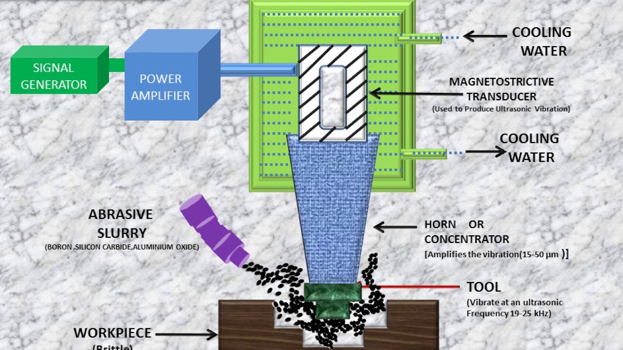
                                                 Ultrasonic machining, or strictly speaking the "Ultrasonic vibration machining", is a subtraction manufacturing process that removes material from the surface of a part through high frequency, low amplitude vibrations of a tool against the material surface in the presence of fine abrasive particles.
Image result for ULTRASONIC MACHINING  definition                                                                                                                                                                                                          The tool travels vertically or orthogonal to the surface of the part at amplitudes of 0.05 to 0.125 mm (0.002 to 0.005 in.). The fine abrasive grains are mixed with water to form a slurry that is distributed across the part and the tip of the tool. 
Image result for ULTRASONIC MACHINING  definition
                                        Typical grain sizes of the abrasive material range from 100 to 1000, where smaller grains (higher grain number) produce smoother surface finishes .....


Image result for ULTRASONIC MACHINING  definition


Image result for ULTRASONIC MACHINING  definition
Abstract
Rotary ultrasonic machining (RUM) has been investigated in machining of brittle, ductile, as well as composite materials. Ultrasonic vibration amplitude, as one of the most important input variables, affects almost all the output variables in RUM. Numerous investigations on measuring ultrasonic vibration amplitude without RUM machining have been reported. In recent years, ultrasonic vibration amplitude measurement with RUM of ductile materials has been investigated. It is found that the ultrasonic vibration amplitude with RUM was different from that without RUM under the same input variables. RUM is primarily used in machining of brittle materials through brittle fracture removal. With this reason, the method for measuring ultrasonic vibration amplitude in RUM of ductile materials is not feasible for measuring that in RUM of brittle materials. However, there are no reported methods for measuring ultrasonic vibration amplitude in RUM of brittle materials. In this study, ultrasonic vibration amplitude in RUM of brittle materials is investigated by establishing a mechanistic amplitude model through cutting force. Pilot experiments are conducted to validate the calculation model. The results show that there are no significant differences between amplitude values calculated by model and those obtained from experimental investigations. The model can provide a relationship between ultrasonic vibration amplitude and input variables, which is a foundation for building models to predict other output variables in RUM.
Ultrasonic MachiningHard Brittle Materials  and Other Challenges
As we all know machine tool, cutting tool, automation and software technology are all advancing. However, one other area of progress affecting manufacturers in ever-greater numbers is the advance of material technology. Machine shops are increasingly being challenged by advanced materials, including composites and hard metals, many of which are difficult to machine.

Traditionally used with abrasive cutting tools, ultrasonic machining is now an option for defined-cutting-edge milling and drilling tools as well. With these tools, ultrasonic’s advantages extend to its aid to chip breaking
Find a professional ultrasonic assisted machining for your application ?
Click Altrasonic Assisted Machining to realize it !

Related image